
In consumer electronics, telecoms, and medical devices, the life cycles of products are shrinking to a matter of weeks or even days. Simultaneously, the precision tolerances required of inner parts – whether they be the heatsinks holding densely-packed chips or enclosures guaranteeing radio frequency signals – are stretching thin, with ±0.01mm the norm. Innovators face an equally ruthless choice: use high precision manufacturing but miss market windows, or go for blazing speed and jeopardize quality, risking costly recalls.
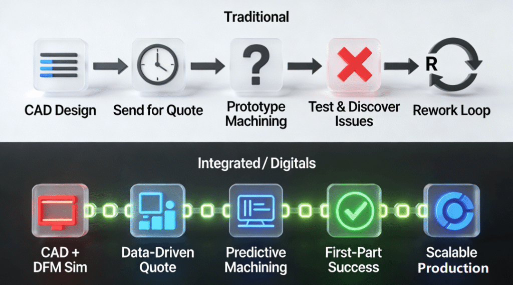
This is because of the false dichotomy between precision and speed. The traditional thinking behind supply chain theory assumes precision and speed to be mutually exclusive elements along a linear spectrum of trade-offs. In other words, the traditional approach offers a binary choice of either “perfect but slow,” or “flawed but fast.” In the world of modern electronics, where multiple physics disciplines must be integrated seamlessly, such thinking falls short. In this article, we will make the case for bridging the gap between precision and speed.
Why is the “Precision Versus Speed” False Dichotomy?
It is widely believed, and at an extremely high cost, that there can be no both precision and speed. However, speed in the context of electronics manufacturing has little to do with the rate of cutting. While a part designed with very thin fins for efficient heat dissipation may indeed result in fast processing, if it does not consider such factors as tool chatter and thermal deformations, its yield rate will be low and multiple expensive molds will have to be redesigned. On the other hand, a manufacturability-oriented design with proper ribs and fillets may look rather conservative, yet it will provide room for stable and efficient processing at high speeds, yielding quality parts. The essence of the argument is that true speed is achieved by succeeding on the first attempt. To achieve that, design should incorporate considerations of precision right from the beginning, not after inspection.
- Why “Speed” at the Expense of Fundamental Precision is Expensive: If there is a drive for faster cycle times on an imperfect process, then there will be waste created by this practice. A piece that is manufactured rapidly but does not meet the tolerances will need to be remachined or scrapped altogether. The saving in manufacturing time is lost exponentially in the requeuing and reinspection. This leads to an endless cycle of inefficiencies and expense. By developing a solid process up front, which is capable of precision manufacturing after being simulated and inspected for quality as the first article, we achieve predictability.
- Accuracy Is What Makes Automation Possible and Scalable: True mass production, especially in high volumes, needs to be automated. Tool changing, palletizing, and robotic handling need to be highly consistent. If you do not have the ability to maintain tight tolerances reliably, then your automated assembly line will come to a grinding halt because of jams, fixture problems, and expensive downtime. Precision does not stand in the way of automation; rather, it facilitates automation. Through precision engineering and machining of electronic components, you make sure that they always fit together perfectly.
- The Domino Effect Downstream to Assembly and Functionality: A component that’s probably solid enough might lead to real headaches on the assembly line. Misaligned screw holes, cracked sealants, or warped heat spreaders tend to create downstream issues. That means extra time spent fixing parts, more product returns, or worse – thermal throttling under load. The savings during initial production don’t match what happens later: debugging errors, dealing with warranty cases, or tarnishing customer trust. When things go wrong after shipping, the cost spikes fast. Building with care and accuracy helps ensure the device works right from day one.
How Does “Design for Excellence” (DfX) Turn Prototyping Into a Predictable Process?
Design for Excellence is the approach whereby the very process of designing ensures that the end result will be successful. There are several components of DfX in relation to electronics hardware: DFM pertaining to tool access and tolerance stack-ups, DFA concerning minimizing the number of parts and fasteners used, and DFT regarding test points and datums. The adoption of DfX ensures that prototyping becomes a predictable process with each iteration being calculated instead of purely experimental. For example, when designing an aluminum electronics enclosure, one can conduct machining stress analysis and adjust geometry accordingly even before proceeding with the cutting process, thus reducing the number of prototypes from 3-4 down to just 1-2, which allows quick-turn electronics machining to take place successfully. The practical application of DfX concepts demands that we have an extensive knowledge of the relevant process. Such knowledge can be conveniently encapsulated in a guide on precision CNC milling services for electronics.
1. DFM: The Link Between CAD and the Machining Tool
DFM necessitates thinking like a machinist. It entails assigning realistic wall thicknesses (such as ≥0.8mm for aluminum) to avoid tool deflections, using chamfers rather than inside edges to accommodate standard machining tools, and strategically assigning tolerances by applying stringent ones only where necessary, especially on mating surfaces. Moreover, it necessitates designing to facilitate fixture placement, along with avoiding shapes that necessitate the use of customized and disposable cutting tools. This foresight ensures that the manufacturer is not forced to make expensive and time-consuming adjustments during later stages.
2. DFA/DFT: Designing for the Next Stages of Life
Whereas DfX goes past the machine shop, Design for Assembly reduces the number of interfaces through the use of self-aligning features and few screws to reduce assembly time and error. Meanwhile, the Design for Test approach involves including datum points directly on the part, enabling easy inspection using the coordinate measuring machine. It may also involve designing access locations for functional test probes. By taking these considerations into account during the design process, the product becomes readily manufacturable, assembled, and tested.
3. The Strength of Digital Twinning and Simulation
Modern-day DfX depends on simulation. Finite Element Analysis could help foresee any deformations in a thin-walled box from machinability or thermal considerations. Computational Fluid Dynamics may be used to simulate air flow in a heatsink concept. In such digital twins, the engineer can run iterations in a virtual space until a high-fidelity result is achieved, without any need to use materials at this stage yet. Virtual prototyping is a powerful way to make sure your prototype doesn’t only have the right shape, but the perfect design inside it as well.
PCB Milling vs. Metal Machining – Do You Have the Correct Precision Process for Your Job?
It is important that the proper precision process be chosen depending on the material used and what it should accomplish. PCB milling and metal machining are distinct areas of science, each of which requires specific parameters. Failure to recognize this may result in an inappropriate solution being offered. It is important to have a decision matrix in order to ensure success, where PCB milling is best suited for creating electrical connection or isolation, with emphasis being placed on trace/space tolerances and layer registration in an ESD safe setting on materials such as FR4. Metal machining is used to create structures, manage heat, and shield from EMI, requiring tight geometric tolerance and excellent surface finish on materials such as aluminum and copper.
1. PCB Milling: The Fine Craft of Subtractive Electronics Creation
PCB milling can be considered a specific case of routing when copper is milled away to produce traces. The accuracy of this technique is expressed by line width/spacing parameters (down to 0.1 mm) and hole precision. This procedure is very sensitive to the speed of work and tool sharpness because any errors may result in tearing the copper or substrate. PCB milling requires a clean and static-free working environment. This technique is particularly suited to creating high-frequency RF PCBs, antennas, and fast PCB prototyping.
2. Metal CNC Machining: Engineering for Form and Environment
Machining metals for electronic components involves mechanical and environmental considerations. The RF shield, for instance, must be machined with accurate and smooth walls to enclose the signal. In another example, the server heatsink would need parallel surfaces that will allow maximum efficiency in conducting heat from its interior. These are all machined parts which require very precise tolerances for flatness, perpendicularity, and true positioning to ensure that their measurements are accurate up to ±0.05mm or even better.
3. The Integrated Approach: Where the Two Worlds Meet
Sometimes, the most sophisticated parts need both manufacturing techniques to make them. The metal base plate could contain machined recesses for the printed circuit board assemblies as well as cooling passages and act as a ground plane at the same time. The housing for the hermetic connector could be machined from aluminum with precisely machined holes but also have slots machined out for the glass seals. Having an understanding of the different considerations of PCBs and metals machining opens up new possibilities for highly integrated design.
Can Data-Driven Process Control Help Overcome Thermal Deformation in High-Speed Milling?
The basic physical phenomenon encountered when milling high-conductivity metals, such as aluminum and copper, is thermal deformation. Heat is generated in the localized milling operation, resulting in the expansion of the workpiece. Once it cools, it will contract, which can deform the thin sections. To solve this problem, the use of a three-tiered system in the form of preventive optimization, proactive compensation, and closed-loop adaptation through data-driven process control is the approach that should be adopted. Preventive optimization involves setting of optimal parameters based on the properties database of materials. Proactive compensation involves thermal-awareness in the Computer-Aided Machining (CAM). In addition, closed-loop adaptation uses in-process measurements to control thermal effects. The scientific challenge posed by these phenomena is fundamental in advanced manufacturing, with key institutions such as NIST providing the benchmarks needed.
1. Prevention: Intelligent Cutting Parameters in a Digital Library
First, it is important to reduce the amount of heat generated. It is not a wild guess. Modern manufacturers possess special machining databases, where there are prescribed specific optimal parameters of spindle speed, feed rate, and depth-of-cut depending on a certain metal or steel type and its heat treatment. These are such parameters, which guarantee thin and easy-to-remove chips taking away the heat from the workpiece, instead of absorbing it. Applying the coolant under high pressure right onto the edge of the tool also helps here because it is both a coolant and a heat sink.
2. Compensation: “Distorting” the CAM Toolpath
Nevertheless, not all the heat can be avoided even if the optimal cutting parameters were used. Therefore, it is necessary to find ways of compensating for it. This can be done by simulating the expected thermal deformation of the machined piece using Finite Element Analysis. Then, applying this simulation, the toolpaths will be made “distorted,” thus producing a wrong part. During machining, it will expand due to temperature rise and contract afterwards. Hence, it will return back to its initial position, which is called nominal.
3. Closed-Loop Control: The Self-Calibrating Machine
In the most sophisticated configurations, closed-loop control is achieved. An on-machine measurement or non-contact probe checks key dimensions of the component either in between operations or even while cutting. When the dimensions tend toward the limit of their tolerances due to worn tools or unpredictable temperature changes, the system can correct the problem through tool offset adjustment or varying feed speeds. Such a system ensures uniformity piece after piece, hour after hour, turning the machine into a smart, self-regulating manufacturing unit.
What Insights Does a True Quote for CNC Machining Tell Us About Manufacturing Preparedness?
While a quotation from an engineering firm for CNC machining may be thought of simply as a number at the end, it actually offers valuable insights into whether the engineering firm is doing due diligence and into the viability of the manufacturing process. The transparent quote breaks down cost by category: materials, non-recurring engineering (programming/setup), and machining cost per unit part. More than that, the quotation also identifies potential manufacturing problems and gives suggested solutions to address them, such as when a design includes deep holes, small holes, or aspects with a high aspect ratio.
This approach indicates a supplier who is co-engineering a solution, thereby de-risking the project upfront rather than through costly rework.
1. Cost Breakdown: The Explanation for the Quote Price
An overall cost figure conceals many essential details. A breakdown of the cost quote identifies the raw material blank price (incorporating scrap factor), engineering efforts for CAM programming and fixtures, and machining hours for each manufacturing step. Such transparency makes value engineering possible. High setup cost indicates combining several parts in one order as a worthwhile option. In case of machining costs being dominant, re-designing using DFM to minimize tool path can provide substantial savings. This cost breakdown promotes a partnership approach aimed at effective cost management rather than mere negotiations.
2. Risks and Mitigation Strategy
The most informative quotes serve as early warning tools. “Deep pocket (5x diameter) needs customized extended tooling that increases tooling cost by $XXX” and “Recommended: Wall thickness should be increased from 0.5mm to 0.8mm to ensure stability” are priceless comments. They describe the geometry into manufacturing feasibility and cost implications. This way, the client can decide which option is preferable. Should ultra-thin walls be acceptable in terms of cost increase and risks involved? Or is it better to increase its thickness somewhat to ensure reliability and reduce costs?
3. The Quote as a Blueprint for Collaboration
A solid quote starts the project right. It names the assumptions, shows how we’ll do it, and gives a clear beginning for talking. Now, the supplier sees the work, studies it deeply, and knows what’s needed. They actually create this plan instead of waiting to be told. Now the buyer moves fast, first action sets the tone. That first move changes everything. We begin with trust, not paperwork.
From 5G Heatsinks to Surgical Robotics – A Case Study of Precision & Speed Synergy
The case study involves a manufacturing project for a large 5G antenna heatsink that uses thin fins. The results from this project showed a 68% yield rate and a delivery period of 6 weeks using traditional manufacturing techniques. Through the use of the integration of a precision CNC system—which incorporates changes in design excellence (DFX), PCD tooling, thermal simulation, and in-process statistical process control (SPC)—it led to a breakthrough result. There was an increase of 98.5% yield rate, a reduction in the lead time of 2.5 weeks, and improvement in the thermal performance by 15%. Thus, one can conclude that investing in the production of precision CNC milling parts results in significant performance, efficiency, and cost-effectiveness benefits.
1. The Problem: Extending Accuracy to Massive Scale
The enormity of the component (400 mm) only increased the difficulty. Conventional machining techniques resulted in progressive thermal distortion over the enormous surface area, with the flatness requirement becoming almost unattainable. Deflection caused by machining the long and slender fins resulted in inaccurate thickness and poor surface quality. There was no progress in the project, failing in both the yield and lead time goals, jeopardizing the delivery to a prominent telecommunications equipment manufacturer.
2. The Systemic Approach: Multi-disciplinary Redesign
The solution involved much more than one specific modification to achieve the desired result. The DfX team introduced the idea of sacrificial ribs for reinforcing the fins in the machining process before being stripped off. Process engineers moved from conventional tooling to Polycrystalline Diamond tooling due to its durability and low cutting temperatures. The CAM programming incorporated several stages to remove material gradually and manage stress, and probe in cycle to take into account any tool wear. A digital thread was developed, connecting CAD, machine, and CMM data together.
3. The Quantifiable Outcome: Performance and Business Metrics Transformed
The outcome proved the systemic solution. The 98.5% yield ratio eliminated waste and rework costs. The 2.5-week delivery time (down from 6 weeks) decreased time-to-market and increased cash flow. The most critical result was, however, the 15% increase in thermal performance, which gave a clear competitive edge in terms of product specification sheets. From the above discussion, one sees how precise manufacturing, through a comprehensive application of engineering principles, doesn’t just help to solve production challenges but helps in the creation of better-performing products as well.
Conclusion
In the case of electronics innovation, “speed vs. precision” does not constitute an unchangeable dilemma, rather it is a matter of optimizing the manufacturing system. Through implementation of integrated precision manufacturing, where manufacturing is embedded in the design and data-controlled process, together with the establishment of highly cooperative supply chain relationships, manufacturers can effectively turn the two contradicting notions of speed and precision into a single source of fast and reliable manufacturing operations.
FAQs
Q: What is the realistic lead time for a working prototype of an aluminum electronics enclosure?
A: It takes about 3 to 5 workdays if the supplier knows what they’re doing. Complex designs can stretch to 7 or 10 days because of tighter tolerances and more detail. That estimate works only if the shop focuses on prototyping and runs both design and production side-by-side.
Q: How do you ensure strong EMI/RFI blocking in CNC metal cases?
A: All surfaces must touch directly – no gaps. CNC ensures flat edges so parts fit together tightly. Surface texture matters too, and it needs to compress properly under gaskets. Avoid material pairs that react electrochemically. Smaller holes help reduce signal leaks at least in theory.
Q: Is it possible to use CNC milling for prototyping and high volume production in the same process?
A: Definitely. It’s one of the biggest advantages that CNC milling allows you to use one single process throughout the product lifecycle – from prototyping (where no hard tooling is necessary) and low-to-medium volume production to high volume production (where precise molds and dies for casting or stamping will be made).
Q: What should you provide in order to get an accurate quote on CNC machining services?
A: Send over a detailed 3D CAD file, STEP or. X_t works best – and a clear 2D drawing with every dimension, including GD&T specs. Include material type, surface finish requirements, and any coating needs. At least in theory, that covers the basics.
Q: How is quality kept high when milling delicate electronics?
A: We start with first article checks using CMMs, track progress by SPC during production, then verify everything with material records. For key projects, we validate processes, conduct audits, and follow AS9100D standards. Quality isn’t just checked at the end – it’s built into how things are made.
Author Bio
The author is a lead manufacturing engineer with more than 12 years of experience in precise manufacturing of consumer electronics and telecom applications, working towards enabling technology companies bring their highly complex designs into reality by developing highly reliable products using innovative supply chain and manufacturing processes. The author leverages his skills in the context of LS Manufacturing, which offers highly reliable, engineering-driven manufacturing services. The team is known for overcoming multi-disciplinary issues while delivering products in volume without any defects. For a full DFMA study and feasibility report of your future electronic parts, upload your CAD models here.